 ar
ar bg
bg hr
hr cs
cs da
da nl
nl fi
fi fr
fr de
de el
el hi
hi it
it ko
ko no
no pl
pl pt
pt ro
ro ru
ru es
es sv
sv tl
tl iw
iw id
id lv
lv lt
lt sr
sr sk
sk sl
sl uk
uk vi
vi et
et hu
hu th
th tr
tr fa
fa ms
ms hy
hy ka
ka ur
ur bn
bn mn
mn ta
ta kk
kk uz
uz ku
ku
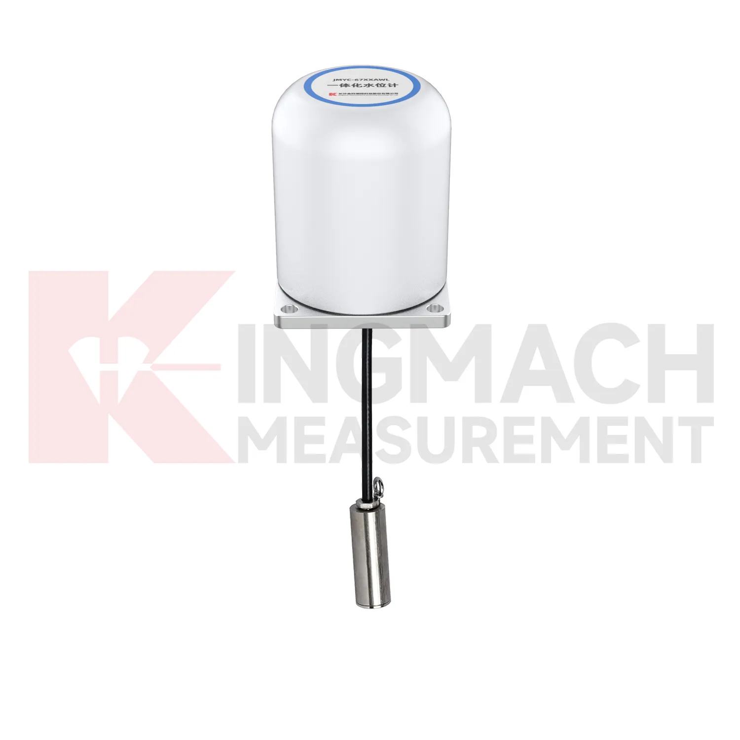
Differential Water Level Gauge
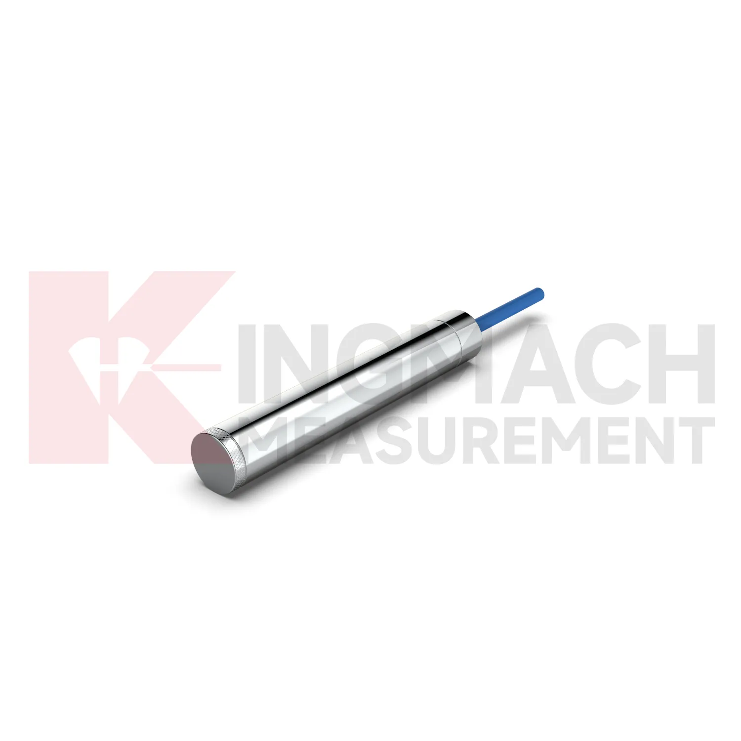
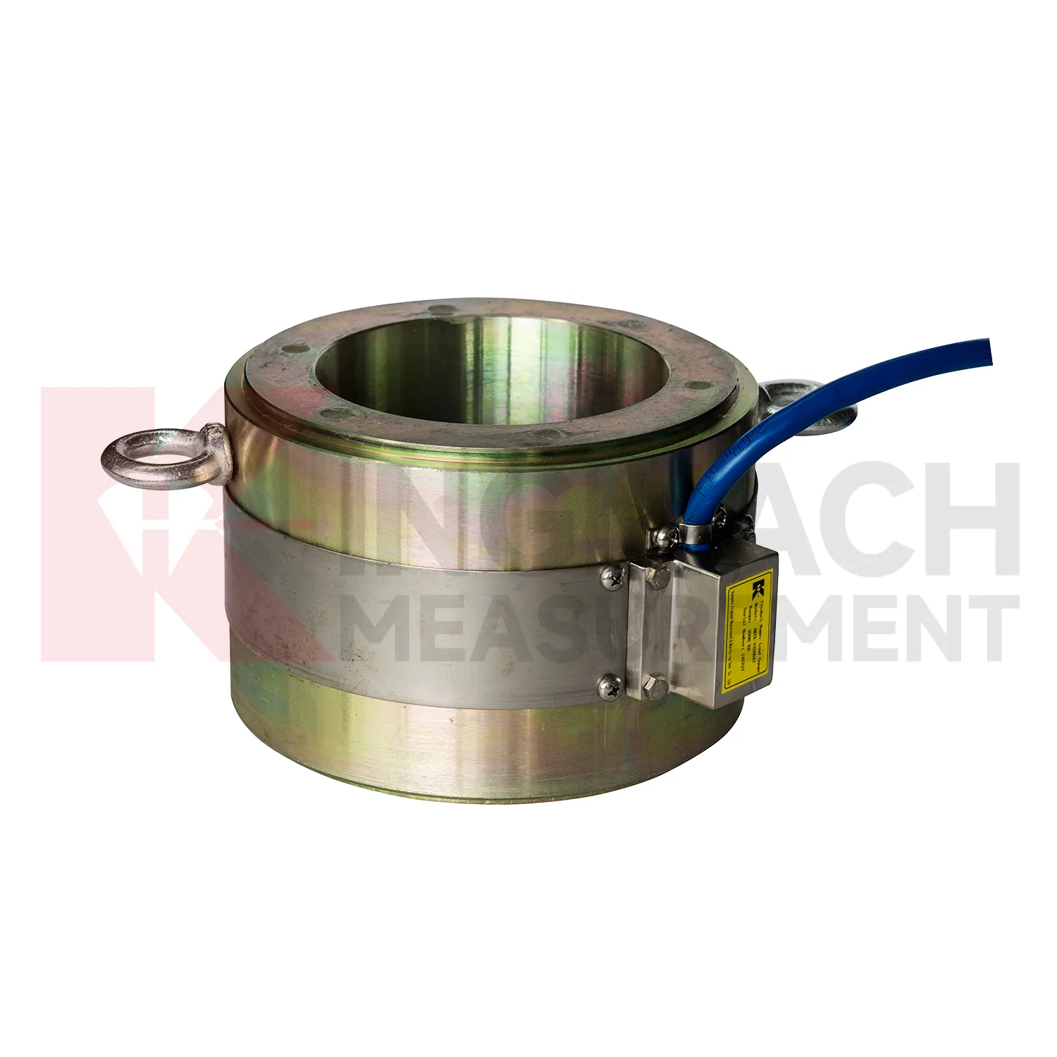
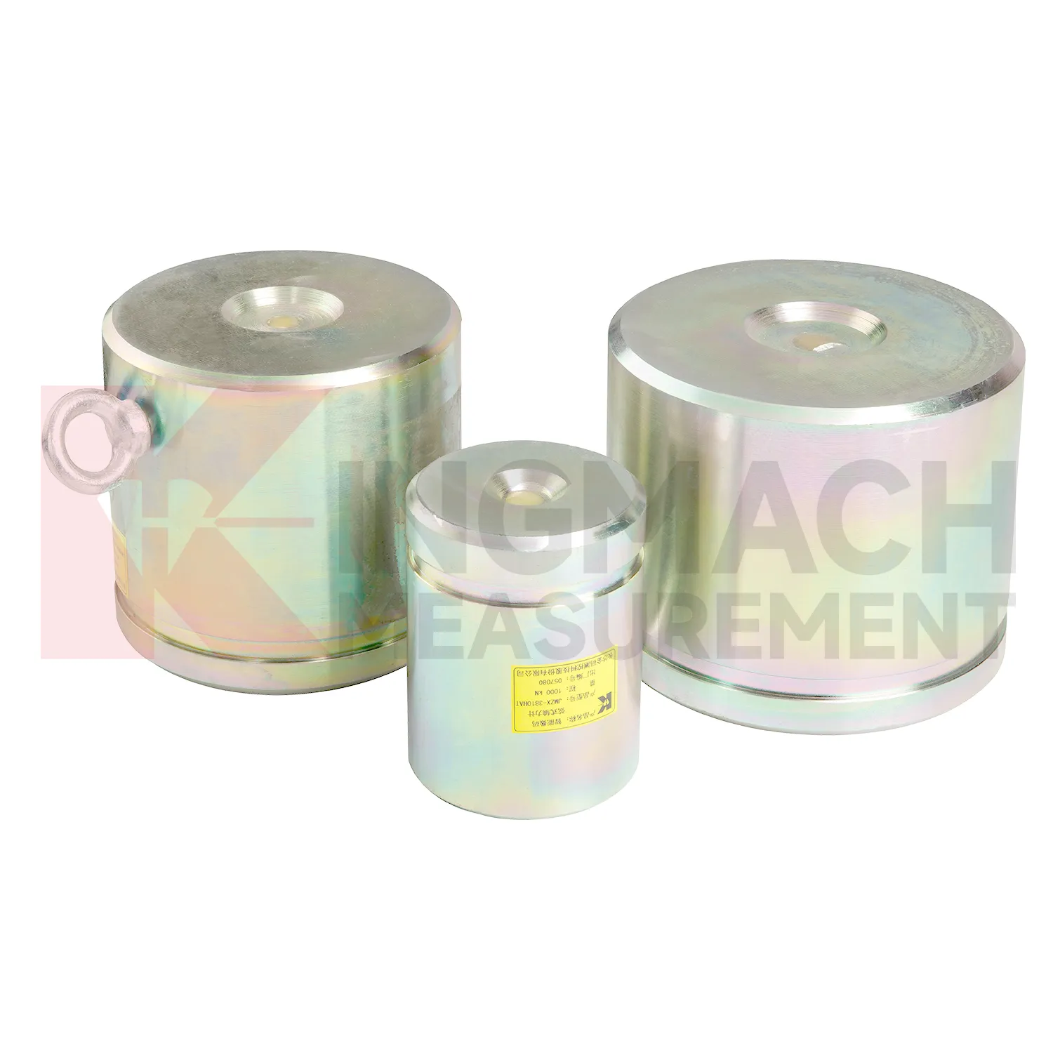
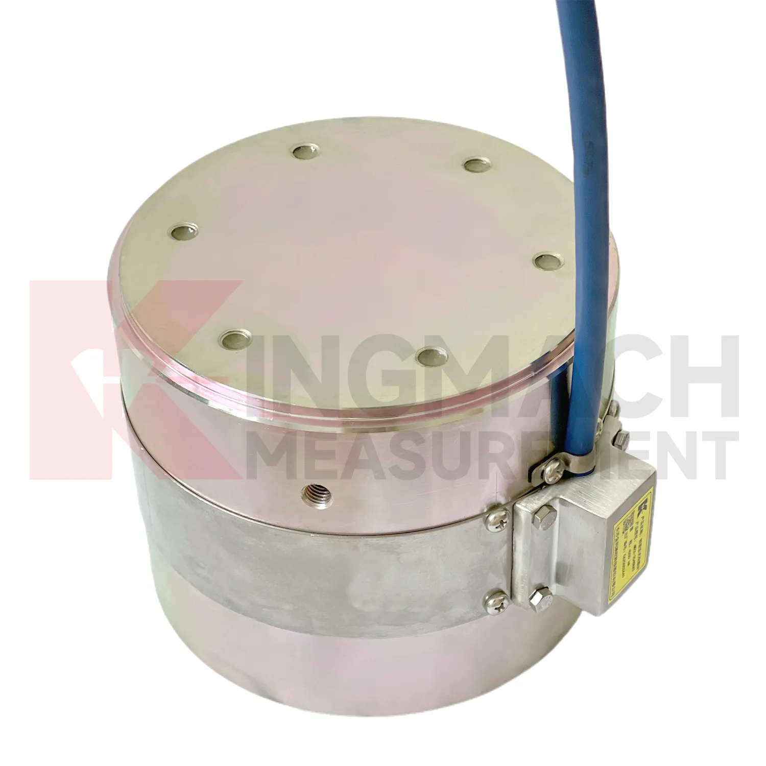
Kingmach Differential Water Level Gauge products are built for projects that need force data with a clear technical trail. The hollow load cell JMZX-3XXXHAT uses an annular multi-string elastic steel structure and is listed from 500 kN to 8000 kN, with 0.1 kN sensitivity on the 500 kN model and 1 kN sensitivity on larger models. Its product file also lists a 50 year design life, digital output, automatic temperature correction, waterproof durability, and storage for 800 measurement records. Those details are relevant in bridge cable force monitoring, anchor testing, and long term structural health monitoring, where the same point may be checked for many years. Kingmach, based in Changsha, supplies sensors with readouts, data loggers, DTUs, and software platforms, so the measuring point can be connected to a wider monitoring network. For a project team, the important value is not a catalog claim. It is the ability to identify the sensor, read the same force channel consistently, compensate temperature influence, and keep a documented record when access becomes difficult after construction. For brand context, Kingmach Measurement & Monitoring Technology Co., Ltd. works from Changsha, Hunan, and its product pages group load sensing with structural health monitoring, engineering monitoring sensors, readouts, data loggers, instrumentation cables, and visualization software. That catalog context matters because a force sensor is often purchased with the equipment needed to read and archive it.
Application of Differential Water Level Gauge
In pile load testing and bearing capacity verification, Differential Water Level Gauge helps track applied force, load stages, unloading response, and residual behavior. The common problem is uncertainty around whether the applied load is centered and whether the recorded value matches the actual force passing through the test system. Kingmach solid load cells such as JMZX-35XXHAT list 1000 kN to 10000 kN ranges, 0.1 kN resolution, and 0.5%FS precision, with overload information listed as 20 to 50%F.S. range overload and 300 to 400%F.S. failure overload. These figures suit heavy test work when capacity margin must be checked before the sensor is installed. During the test, the record should include each loading step, hold time, unloading step, zero check, temperature, and any change to the bearing arrangement. Pairing the load record with settlement readings gives a clearer view of pile response. After the test, the documented calibration coefficient and instrument identity help keep the acceptance file defensible. Test reports should also record jack pressure, settlement response, load rate, hold duration, and any adjustment to the reaction system. These records help engineers identify whether an unusual load value came from the pile, the loading setup, or the measurement chain.
The future of Differential Water Level Gauge
The next stage for Differential Water Level Gauge in infrastructure monitoring is tighter integration with site data systems. Smart sensors already store model data, calibration coefficients, zero values, temperature readings, and measurement records on selected Kingmach products. The practical path is to connect that identity data with 4G, LoRa, wired acquisition, or 5G gateways, then place the force trend beside displacement, settlement, pore pressure, and rainfall in the same review screen. This matters because future warnings will be less about one limit value and more about patterns: force rising after excavation, anchor load falling after heavy rain, or bridge cable force drifting during seasonal temperature cycles. Digital twin models can use those readings when the sensor location, range, and calibration background are reliable. Standards and owner specifications for structural health monitoring are also becoming more data traceability focused, which favors instruments that can carry their own calibration identity and remain readable through long service periods.
Care & Maintenance of Differential Water Level Gauge
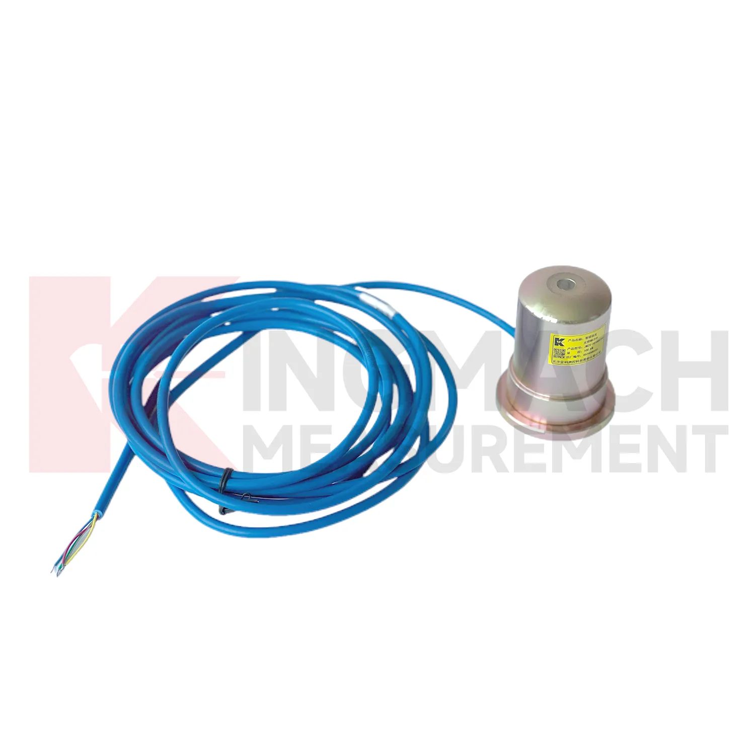
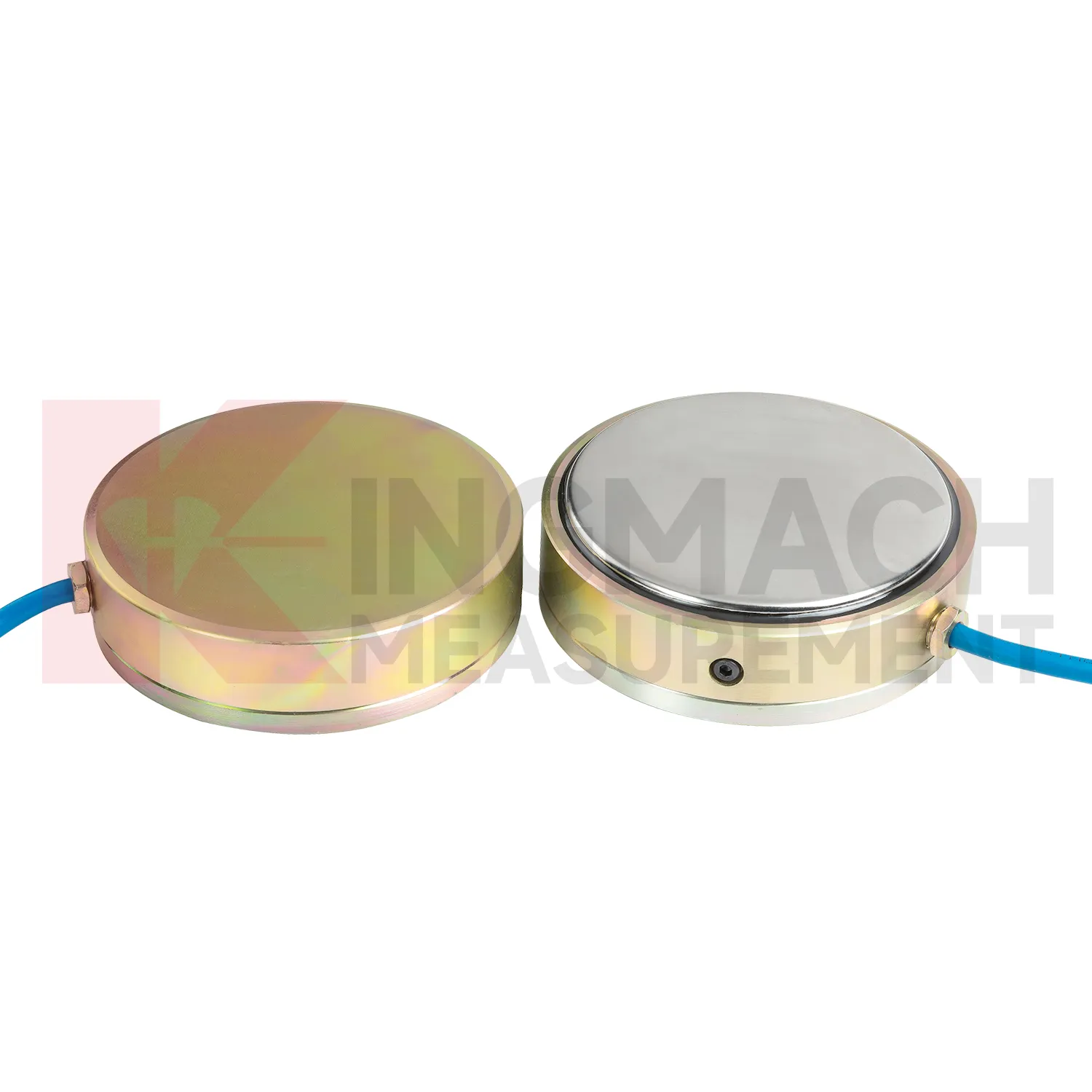
For Differential Water Level Gauge in dam, slope, and embankment monitoring, long term maintenance should emphasize water resistance and traceable records. Some Kingmach load and pressure products list a 50 year design life, but cables, connectors, junction boxes, and exposed labels may age faster than the sensing element. During installation, keep the sensing face clean, avoid impact, secure the cable route, and document depth, location, orientation, and initial reading. Earth pressure cells with 0.3 MPa to 8 MPa ranges and 0.5%FS pressure accuracy should be checked against design pressure and burial condition. During operation, inspect after heavy rain, reservoir level change, freezing weather, nearby excavation, or maintenance work. Look for water entry, cable abrasion, rodent damage, connector corrosion, and channel mix-ups. Readings should be compared with water level, seepage, settlement, and slope movement. A slow drift may be real ground behavior, but only if the field hardware remains in good condition.
Kingmach Differential Water Level Gauge
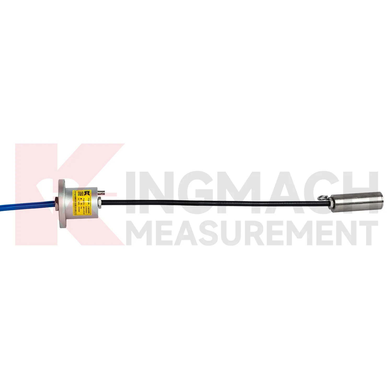
Differential Water Level Gauge can be treated as a field witness for hidden force transfer in civil structures. Concrete, steel, soil, cable systems, and hydraulic loading may all look calm while the internal load path changes. Kingmach products in this category cover hollow load cells for anchors and cables, solid load cells for compression and pile testing, axial force meters for steel support loads, and earth pressure cells for contact pressure. Each type answers a different site question. Has the anchor lost tension? Is a pile test load centered? Is an excavation support taking more force after the next soil layer is removed? Is water pressure pushing the retaining structure harder after rain? The strongest monitoring records combine the sensor model, calibrated coefficient, zero value, temperature, reading time, and construction stage. That record gives owners a way to compare today with last week, last season, or the previous loading step, instead of relying on a single inspection note.
FAQ
Q: When is a solid Differential Water Level Gauge more suitable than a hollow type? A: Solid models are commonly used for compression load, pile load testing, bridge pier support checks, and heavy bearing capacity measurement. Q: What specifications does the Kingmach solid load cell list? A: The JMZX-35XXHAT line lists 1000 kN to 10000 kN ranges, 0.1 kN resolution, 0.5%FS precision, and -30°C to 80°C working temperature. Q: How much overload margin is listed? A: Product information lists 20 to 50%F.S. range overload and 300 to 400%F.S. failure overload. Q: What installation errors affect accuracy? A: Eccentric loading, uneven bearing plates, side load, cable pulling, and missing zero records can all distort results. Q: What records should be kept for acceptance? A: Keep calibration coefficient, model, serial identity, load stages, temperature, zero value, and readout setting.
Reviews
Michael Anderson
The strain gauges and load cells are extremely accurate and stable. They performed very well in our bridge monitoring project. Highly recommended!
James Thompson
The tiltmeters and accelerometers are very sensitive and provide precise data. Perfect for our structural health monitoring system.
Latest Inquiries
To protect the privacy of our buyers, only public service email domains like Gmail, Yahoo, and MSN will be displayed. Additionally, only a limited portion of the inquiry content will be shown.
Isabella***@gmail.comGermany
Hello, we are evaluating weir flow meters for a water management project. Please share accuracy deta...
Ava***@gmail.comAustralia
Hi, I am looking for reliable tiltmeters and accelerometers for structural health monitoring. Please...
Related product categories
- calibration of load cell theory
- load cell failure
- load cell technology
- strain gauge load cell wiring
- diagram 4 wire load cell wire connection
- load cell accuracy calculation
- load cell amplifier circuit
- load cell calibration procedure
- load cell excitation voltage
- load cell unit of measurement
- mounting load cells
- strain gauge with load cell